Challenges of Designing Circuits for Flexrigid
Circuits for Flexrigid
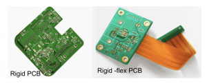
Rigid-flex circuit boards combine the benefits of rigid PCBs with flexible circuitry that can bend, flex and fold. They allow manufacturers to reduce the number of point of failure interconnects in their products and are ideal for medical and military applications (Figure 2).
When designing circuits for flexrigid, it is important to consider mechanical design requirements that will impact how the product performs and fits in the final enclosure. For example, the thickness of the flex section and its relationship to the stiffeners used in the rigid section can affect the product’s performance. It is also important to keep in mind the interaction between the flexible and rigid sections of the board when routing signals to maintain signal integrity.
Another key challenge is the need to ensure the rigid-flex board can handle electrical and thermal requirements of the product it will be used in. This can be accomplished by using advanced materials that provide superior conductivity and thermal stability while remaining as lightweight as possible.
Rigid-flex PCBs can be used in many different types of devices, from telecommunications to consumer electronics to aerospace systems. These devices must be reliable and withstand shocks, vibrations, and drops when in use or in transport. To do so, flex-rigid PCBs must use fewer components and connectors which can increase the overall reliability of the finished product.
Challenges of Designing Circuits for Flexrigid
Achieving this requires careful engineering of the entire circuit board, including the choice of materials, layer stack up, and component placement. For instance, choosing a high-quality dielectric material is key to minimizing signal interference and controlling impedance in the flex region. It is also important to avoid shorts and grounding problems by using proper copper distribution and avoiding sharp turns in the circuit board layout.
Finally, it is vital to ensure that the flexible PCB will meet electromagnetic interference/electromagnetic compatibility (EMI/EMC) standards and guidelines. This can be achieved by using a good signal grounding technique and keeping the copper traces and rigid components as close together as possible to minimize coupling and crosstalk between them.
While all of these challenges are unique to flexrigid designs, they are not insurmountable. Having the right tools and working with experienced PCB manufacturing partners can help designers overcome these challenges, resulting in robust, reliable products. By leveraging an ECAD/MCAD platform that provides integrated CAD and MCAD tools to enable design verification, designers can quickly verify that their circuits will fit into the final mechanical enclosures.
This will eliminate costly rework and ensure that the final product meets customer requirements. Altium Designer is one such tool that offers a complete range of layout features, enabling users to model the polyimide flexible circuit zone, transition zone and integration into rigid-flex PCBs. Click the button below to learn more.