How Do Flex PCBs Handle Prolonged Exposure to Vibration?
Flex PCBs Handle Prolonged Exposure to Vibration
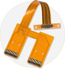
As the name implies, flex PCBs are designed to be flexible. They’re used in consumer electronics like tablets, phones and cameras, as well as industrial equipment, requiring them to withstand vibration, shock and other environmental factors. In addition, flex circuits are often required to bend and twist in their respective applications, so they must be able to withstand sustained periods of movement without causing damage or malfunctions.
Prolonged exposure to vibration can cause cracks in the conductor layers of a flex pcbs, or even a collapsed traces in some cases. To prevent these issues, it’s important to plan out your layer stack properly. This involves avoiding stacked traces, ensuring proper copper thickness and impedance in both the rigid and flex sections of the circuit, and following proper bend guidelines.
In addition to making sure the layer stack is planned out correctly, it’s also a good idea to use an etching process that will be tolerant of the increased expansion and contraction that occurs in flex materials. This can be achieved by using pad-only plating, which deposits copper only on the pads/vias. This allows for better control of the copper thickness, impedance and etch yields, as well as improved assembly and design flexibility.
How Do Flex PCBs Handle Prolonged Exposure to Vibration?
Another issue that can occur with flex pcbs is I-beaming, which can result in stress points and cracks in the copper conductors in the flexible section of the circuit board. This is caused by traces being too close together, which creates an uneven distribution of force when the circuit bends. To minimize this, it’s important to keep traces as wide as possible in the non-flex areas of the circuit board, and then tapering down to narrower traces in the flex sections. This will help to keep the copper from cracking when bending.
Finally, it’s important to avoid using discontinuities such as holes, cutouts, slits and strip lines in the bend area of a flex circuit. These can all put stress on the copper and lead to failure, especially in the flex sections of the circuit. To reduce the chance of these issues, try to make all of the traces on your flex circuit narrower as you get closer to the bend region. This will reduce the amount of copper that’s subjected to stress during a bend, and eliminate any potential failures due to I-beaming or other types of cracks in the copper conductors.
If you’re considering a flex or rigid-flex circuit, it’s important to choose a turnkey PCB manufacturer that is experienced with manufacturing these types of boards. This can ensure the highest quality and performance of the finished product. The manufacturer you choose should be able to provide a quality-to-cost ratio, as well as offer turnkey fabrication and assembly services to meet your specific needs. Lastly, make sure to select a company that has all the necessary industry certifications and registrations to guarantee their work meets all relevant standards. The best way to find the right manufacturer is to visit their factory and see their capabilities for yourself.