What is a Circuit Board Assembly?
Circuit Board Assembly
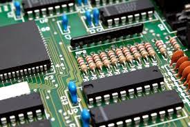
The copper lines on a bare printed circuit board (PCB) called traces connect various electronic components. They run signals between them, allowing the circuit board to function in a specific way designed by the engineer. This is how a PCB assembly becomes an electronic device like a smartphone, tablet, or camera.
The process of turning a bare circuit board into an electronic device is known as printed circuit board assembly or PCBA for short. It consists of multiple stages that transform the bare circuit board into a finished product. These stages can be broadly categorized into pre-assembly, during assembly and final assembly.
During the pre-assembly stage, the assembler creates a schematic diagram of the circuit board. This is the blueprint of the circuit board and specifies the location of each component for optimal signal flow and to prevent interference. The design should also consider the thermal and mechanical requirements of the circuit board. For example, a PCB used for automotive electronics must be rugged to withstand high temperatures and shocks.
What is a Circuit Board Assembly?
Once the design is ready, it’s submitted to a CCA or PCB manufacturer for manufacturing. The company will analyze the bill of materials (BOM) to ensure that the design meets all required specifications for a successful PCBA. They will also run a design for manufacturability check (DFM) to spot any problems that may affect the functionality of the final product.
The next step involves creating a stencil for the circuit board. The stencil is a thin layer typically made of stainless steel or other durable material. It has openings corresponding to the locations where solder paste needs to be applied on the board. Once the stencil is ready, the assembler places various SMDs or electronic components onto the circuit board using an automated machine. The most common SMDs are resistors, diodes, and integrated circuits, but larger components such as mechanical parts or connectors may use through-hole technology.
Circuit board assembly is a fundamental process in the manufacturing of electronic devices, playing a critical role in the functionality and performance of various technological products. From smartphones to computers, from medical devices to automotive systems, circuit boards serve as the backbone, enabling the seamless integration of electronic components and facilitating the flow of electrical signals.
After the SMDs are placed, the assembler will apply solder to each connection on the board. Then, the assembler uses one of three possible soldering methods to secure the components. Surface mount technology (SMT) assembly is the most common method because it allows a higher density of components than other methods. Through-hole technology is the alternative to SMT and works well for components with long leads that need to be soldered to the circuit board. The assembler can also use mixed technology, which uses both SMT and THT.